An engineering drawing functions as the language for engineers to communicate technical requirements. These drawing requirements are directly linked to the engineering design intent. The design engineer supplies the necessary specifications in the drawing to meet customer needs. The drawing serves as a resource for downstream users, including manufacturers, quality engineers, assembly engineers, suppliers, and other cross-functional teams. Manufacturers require it for physically producing the part, quality engineers use it for inspecting specifications, and assembly engineers rely on the drawing for fitting parts onto machines. Suppliers also depend on the drawing to supply parts based on requirements.
Creating handmade drawings used to be a challenging task. However, with the availability of advanced software in the market, modeling complex 3D parts along with detailed drawings has become considerably easier. The drawing is a sheet containing figures, dimensions, tolerances, bill of materials, and other specification notes related to the part or assembly.
Considered a legal document, the drawing helps understand desired objectives from different cross-functional teams, which are critical to meeting customer expectations. Deviating from drawing specifications is not advisable, as it could lead to rework or rejection of the part. Different views, utilizing methods like the first angle and third angle projections, are used to show details in the drawing sheet.
The drawing sheet should have sufficient space to display details, and different drawing scales can be used if views are smaller or larger. The drawing sheet can be portrait or landscape based on sheet size selection, with A4, A3, A2, A1, and A0 being commonly used sheet sizes for engineering drawings.
It’s challenging to imagine the manufacturing of parts without an engineering drawing. Orthographic projection and Perspective projection are commonly used methods, with the Orthographic projection method being most prevalent among mechanical design engineers. Nowadays, it is a general practice to include a 3D view in the drawing for better visualization, which can be Isometric or Axonometric. Types of views include sectional views, detail views, auxiliary views, and uninterrupted views in an engineering drawing.
An engineering drawing may consist of one sheet or multiple sheets based on the complexity level of the parts. Multiple sheets are used for assembly, fabrication, machining, and painting purposes.
Below is an example figure demonstrating engineering drawing views (front view and side view)
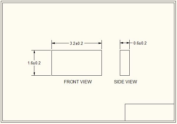
The depicted figure represents a basic plate with allowable tolerance. If tolerances are outside the specified range, the part may be rejected. Additional requirements, such as plating notes, painting notes, surface finish, and material callout, must also be met. The responsible party will not allow the part to pass the gate until it meets all requirements. All cross-functional teams or departments responsible for making this part must adhere to the drawing requirements. This document aims to enhance understanding of engineering drawings. Wishing you very happy learning!
Hi, this is a comment.
To get started with moderating, editing, and deleting comments, please visit the Comments screen in the dashboard.
Commenter avatars come from Gravatar.